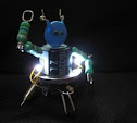
Bluetooth Controlled Mobot using Z8F0823 and LMX9838.
It's supposed to be my entry for a friendly competitions of "sumobots". But, I wasn't able to make it "autonomous" on time for the event. It only have four sensors on each corner to detect "black" lines, but no sensor for detecting an opponent. And so that I can still test the hardware, I just made it manually controllable by using my phone's bluetooth. The bluetooth module is the same circuit I used in my BT minibot . I also used the same python S60 script for my N6120c (Symbian phone) controller.
As inspired by Simple SD Audio Player by ChaN, this project uses Microchip's PIC18F2550 to read RIFF WAVE files, and display some file information on the N6610 LCD; And then it will play the audio itself through PIC's PWM with a simple RC filter on the output pin. The hardware actually comes from my previous project, and I just attached a ready-made audio amp (w/ speaker) for the demo. Schematic: Due to PIC's peripheral limitations, I only set the PWM frequency to 187.5kHz and not the 250kHz carrier frequency originally used by ChaN, because it's the maximum PWM frequency than can still get an 8-bit resolution of the duty cycles (=48MHz/256). It is also possible to use R-2R ladder in stead of (low-pass) filtering the PWM output since there still enough unused digital output pins for this approach. On the software part, I wasn't able to make a good data buffering as good as what ChaN did. It's noticeable with WAVE files with higher bit-rates (=SampleRate*NumChannels*BitsPerSample). Nevertheless, it can still support up to 48kHz sampling rate, but with only Mono channel and 8-bits/sample resolution.
It is similar to my first PIC SD BMP Reader , and almost the same circuit except for the LCD. This time I now use a Nokia 6610 LCD. The LCD is capable of displaying 4096 colors, but for code simplicity I just operate it at 8-bit (256 colors) resolution.
Diagram: This project is capable of reading bitmap file using common format (24-bit per pixel), with size (width and height) equal to or less than 132 pixels at both side.
This project uses Microchip's PIC18F2550 and Nokia 3310 LCD to read and display images from BMP files on the SD/MMC cards. Although the display itself is monochrome, it still supports 24-bpp (bits per pixel), 8-bpp, 4-bpp, and 1-bpp (monochrome) Bitmap files (*.BMP) with size of 84x48 pixels. It uses the Petit FAT File System Module by ChaN.
The application reads picture-files in standard Windows BMP-format from a SD-Card and shows them on a 2.8" color-LCD-module (320*240 px).
The application also uses the FAT File System Module by Chan, on which M. Thomas ported to work on STM32 SPI interface. Additional information about this project can be found on the link above. Some of the minor modifications I made were:
I've modified the LCD driver so that it will work on my unit. My unit got the ILI9320 LCD controller.
I didn't utilize the USART interface (but this can be easily enabled in the code). In stead of sending the "information" through this interface , some of them are being displayed on the LCD itself (e.g. bitmap filenames).
I've enabled the two push-buttons on the board. The first one toggles between "Play" and "Pause"; and the other one is to "Restart" the "slide-show" from the beginning.
FreeRTOS Demo on Mini-STM32 kit (STM32F103RBT6 with 2.8" TFT LCD).
My initial attempt of porting the FreeRTOS Demo was considerably a success. But later on, I found out that the version used of STM32 standard peripheral library was already obsolete. And so I didn't anymore continue with that. In stead, I opt to use the latest Firmware version which is v3.2.0 (Mar-2010), and combine it with the latest FreeRTOS source code - v6.0.4.
It wasn't easy for me to start the Keil uVision project from scratch (almost). On the brighter side, I already got familiarized with STM32 code libraries because of this activity. It's mostly trial-and-error approach. But luckily I stepped into this guide of porting the FreeRTOS source: Running FreeRTOS on the Keil MCBSTM32 Board with the RVMDK Evaluation Tools
Here's the result. After few seconds of displaying the "Powered by FreeRTOS" message, the demo will now display the status of all tasks. If there's no error occurred, it will show "PASS" and the 'jitter' in the processing of timer interrupt (timertest.c). For the USART test (comtest.c), there's a "loopback" test of transmitted and received characters. Simply short the pins 2 and 3 (RX and TX) of CON1 in the Mini-STM32 board. Otherwise, it will show "ERROR IN COM TEST" message.