Saturday, May 22, 2010

PIC18F SD WAV Audio Player

As inspired by Simple SD Audio Player by ChaN, this project uses Microchip's PIC18F2550 to read RIFF WAVE files, and display some file information on the N6610 LCD; And then it will play the audio itself through PIC's PWM with a simple RC filter on the output pin. The hardware actually comes from my previous project, and I just attached a ready-made audio amp (w/ speaker) for the demo.
Schematic:
Due to PIC's peripheral limitations, I only set the PWM frequency to 187.5kHz and not the 250kHz carrier frequency originally used by ChaN, because it's the maximum PWM frequency than can still get an 8-bit resolution of the duty cycles (=48MHz/256). It is also possible to use R-2R ladder in stead of (low-pass) filtering the PWM output since there still enough unused digital output pins for this approach.
On the software part, I wasn't able to make a good data buffering as good as what ChaN did. It's noticeable with WAVE files with higher bit-rates (=SampleRate*NumChannels*BitsPerSample). Nevertheless, it can still support up to 48kHz sampling rate, but with only Mono channel and 8-bits/sample resolution.

demo video:


Source code(PICC-18) with and without LCD: PIC18 SD WAV Audio Player

My on-going project: currently porting the code to STM32F103RB for additional features.

Some useful software (shareware) tools:
TextAloud - Text to Speech software
Switch Sound File Converter-multi format audio file converters

Tuesday, May 11, 2010

PIC SD BMP Reader II

It is similar to my first PIC SD BMP Reader , and almost the same circuit except for the LCD. This time I now use a Nokia 6610 LCD. The LCD is capable of displaying 4096 colors, but for code simplicity I just operate it at 8-bit (256 colors) resolution.

Diagram:
This project is capable of reading bitmap file using common format (24-bit per pixel), with size (width and height) equal to or less than 132 pixels at both side.

demo video:


Source code + diagram: PIC18 SD BMP Reader 2.rar


similar project at Hack-a-day: How-to: Digital picture frame, 100% DIY
-it uses PIC24FJ64 in stead of pic18f2550

Saturday, May 8, 2010

PIC18 SD BMP Reader

This project uses Microchip's PIC18F2550 and Nokia 3310 LCD to read and display images from BMP files on the SD/MMC cards. Although the display itself is monochrome, it still supports 24-bpp (bits per pixel), 8-bpp, 4-bpp, and 1-bpp (monochrome) Bitmap files (*.BMP) with size of 84x48 pixels. It uses the Petit FAT File System Module by ChaN.

Diagram and simulation:
Actual circuit:


Demo video:


forum link: Petit FAT File System (w/ Proteus ISIS simulation)

Source code(PICC18) + simulation(ISIS) + others: PIC18 SD BMP Reader.rar

references for BMP file format:
Wiki BMP file format
atlc.sourceforge bmp format
MSDN Types of Bitmaps

Saturday, April 24, 2010

Mini-STM32 Digital Picture Frame

The original source code for this project is copied from Martin Thomas' Simple STM32 Digital Picture Frame
The application reads picture-files in standard Windows BMP-format from a SD-Card and shows them on a 2.8" color-LCD-module (320*240 px).
The application also uses the FAT File System Module by Chan, on which M. Thomas ported to work on STM32 SPI interface. Additional information about this project can be found on the link above.


Some of the minor modifications I made were:
  • I've modified the LCD driver so that it will work on my unit. My unit got the ILI9320 LCD controller.
  • I didn't utilize the USART interface (but this can be easily enabled in the code). In stead of sending the "information" through this interface , some of them are being displayed on the LCD itself (e.g. bitmap filenames).
  • I've enabled the two push-buttons on the board. The first one toggles between "Play" and "Pause"; and the other one is to "Restart" the "slide-show" from the beginning.

demo video:


Modified Source Code (Keil RVMDK + uVision 4): Digital Picture Frame.rar

Friday, April 16, 2010

FreeRTOS on Mini-STM32

FreeRTOS Demo on Mini-STM32 kit (STM32F103RBT6 with 2.8" TFT LCD).


My initial attempt of porting the FreeRTOS Demo was considerably a success. But later on, I found out that the version used of STM32 standard peripheral library was already obsolete. And so I didn't anymore continue with that. In stead, I opt to use the latest Firmware version which is v3.2.0 (Mar-2010), and combine it with the latest FreeRTOS source code - v6.0.4.

It wasn't easy for me to start the Keil uVision project from scratch (almost). On the brighter side, I already got familiarized with STM32 code libraries because of this activity. It's mostly trial-and-error approach. But luckily I stepped into this guide of porting the FreeRTOS source: Running FreeRTOS on the Keil MCBSTM32 Board with the RVMDK Evaluation Tools

Here's the result. After few seconds of displaying the "Powered by FreeRTOS" message, the demo will now display the status of all tasks. If there's no error occurred, it will show "PASS" and the 'jitter' in the processing of timer interrupt (timertest.c). For the USART test (comtest.c), there's a "loopback" test of transmitted and received characters. Simply short the pins 2 and 3 (RX and TX) of CON1 in the Mini-STM32 board. Otherwise, it will show "ERROR IN COM TEST" message.

Source Code (Keil RVMDK + uVision 4): FreeRTOS on MINI-STM32.rar

Friday, April 9, 2010

Mini-Term

I've recently bought a Mini-STM32 kit for the purpose of learning ARM-based MCUs. These development kits were from China and then locally distributed by DIY Hobbyist Corner at an affordable price.
After playing with the example codes, including the uCOS/uCGUI demo, I came up with this Mini UART (serial) Terminal application.

I just utilized the source/library for OS of the uCOS_DEMO since I still don't understand how it works. Luckily I got a copy of uCGUI manual and so I manage to make modifications on the existing sample GUIs (graphical user interface). And later, I'm also able to design my own GUIs.
The USART interface is not difficult to learn since it's almost similar to what other microcontrollers is using. Therefor, it's also easy "porting" the USART code (using standard C language) from my previous MCUs to this STM32 MCU.

The application uses the touch-screen capability of the kit for the keypad interface. However, because of the small LCD area, it's impractical to design the keypad as a full featured "qwerty" keyboard. What I did was just provide alternate characters for most of the existing keys.

"Caps" key pressed and USART baudrate chage:
"QWERTY" key toggled and MainForm minimized(showing desktop background):
Alternate keys/symbols and movable dialog:

It's also possible to use a "gender changer" (DB9 female to DB9 Male) on CON1 of the kit to make it resembles as a common PC serial port.
A problem may also raises because of the possibility that the touch-screen response will vary with different units. So, I added an optional "touch-screen calibrate" at start-up. This option can be found on "miniterm.h" header (the "calibration" code is also copied from one of the demo/example codes).

Source Code (using Keil RVMDK + uVision) download: mini-Term.rar

forum link: Mini STM32 with 2.8 LCD and touchscreen

Monday, February 22, 2010

MSI Wind 12 Internal HSDPA (3.5G) Modem Mod

Ever since Wind12 series was introduced in the market, I always see in most of the reviews for these products announcing that these units have SIM card slot found underneath the battery pack. Yes I'm also aware that the 3G modules are only optional, but when I checked my Wind U230 I noticed that the SIM slot actually has no SIM connector inside. Nevertheless, it is true that there's an extra PCIe-mini card slot (intended for 3G modem module) found beside the harddisk. This is a great candidate for circuit modding on which I've already made one. =)

I've dissected my Smart Bro (Huawei E1553) modem for the sake of this mod. Anyway, these USB dongles are relatively cheap nowadays. AFAIK, pcie-mini card-type modems cost 3-4 times more compared to usb-types. Before doing the actual mod, I was still not sure whether this will work on 3.3V supply instead of the common 5V of USB ports. Since I cannot find its electrical specs, I just test it on actual. And, fortunately, it works!


I'm using pins 36 and 38 of PCIE mini card connector for the USB functionality of this port. And for the USB supply, I tapped 3.3V and GND on capacitor C236.This 3.3V supply for the pcie-mini card is automatically turned off during system standby.

There's also a disable pin function for the host to disable the pcie-mini card. It is W_DISABLE# on pin 20. It is held low during boot up of the unit. Also during boot-up, the BIOS will check if there's a load on the pcie-mini's 3V3 output. If it doesn't see any load on the 3V3 bus, the unit will cut-off the 3.3V supply all throughout. Therefor, pressing Fn+F10 keys combination without "load" on the 3V3 will not cause this pin to go to logic high. For now, I'm not utilizing this pin since my "enable circuit" is not yet working. The enable circuit is basically using a p-channel mosfet, which is the same with the bluetooth mod. However, the mosfet I currently have doesn't operate well with only -3.3V Vgs (i.e. doesn't turn on properly). BTW, the enable logic for this pin 20 is opposite of what the previous mod have. Meaning, low (0V) on pin 20 corresponds to "module disabled", and high (3.3V) is "enabled".

I was also got bothered of whether the internal antenna of the modem may not be able to get a good signal strength since Wind12 chassis has metal backbones and the plastic cover itself has conductive coatings. But, there was a U210-lite user who ask me to solder his usb hsdpa modem inside his unit. And I'm quite satisfied with the result even if we didn't wire and reposition the antenna of his modem.
I managed to get coaxial wires (hoping that these wires are similar to what WiFi adapters and actual 3G modems are using). Unfortunately, after finishing the mod and testing the modem, from the usual RSSI of -85dBm (before placing the modem inside the unit) it drops to -90dBm(sometimes -95dBm to -100dBm with SUN network) =( . I'm already anticipating this result. The important is that I can still surf the net (and other online stuffs) without the unexpected disconnection.
Actually, I'm not sure if the second one is really another antenna of this modem but assumed it is since it's not connected directly to GND. We even tested hsdpa modem without this and still works surprisingly.

I've placed the two antennas in between the touch pad and the right speaker, and put some spaced in between the two. I've also repositioned the modem in such a way that SIM card can easily be accessed by just removing the upgrade panel of this unit.

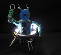
Finally, the complete internal hsdpa modem mod (somewhat "messy").

Fn+F10 combination is now working (the symbol appears on the bottom right of the screen). The LED indicator, which is shared with WiFi, turns yellow. It turns to blue for WiFi and light-blue when both are enabled. (note: my hsdpa modem is always enabled in my present mod)


----------------------
03/01/10 update:
Now I have the extra time to revisit this mod. It seems that it's better (in term of signal reception) for the second antenna(?) to be soldered directly to usb modem instead of using coax wire. Below is my latest adjustment. It looks "presentable" now compared to the previous circuit.
I also tried using different mosfet (IRLML5103 SOT23 package) for the enable/disable function. Although I can now toggle the whole circuit by Fn+F10 keys, it's not a full success yet since my U230 encounters frequent usb disconnection of this modem. I'm not sure of the exact reason of this problem, so I just put back the previous hardware (i.e. Vcc supply) configuration.