Instead of drawing only the edges of a polyhedron, this time we draw the faces and 'fill' it with corresponding colors. This demo now uses a dsPIC (16-bit and 40MIPS core) for "faster" and "smoother" graphics in the N6610/N6100 LCD (w/ pcf8833 controller). See "lcd6610.h" for the used pinouts.
There are several ways of "hidden surface removal". The easiest way, and most appropriate for drawing convex polyhedron is the use of Backface culling. "Backface" will determine whether a surface (e.g. triangular face) is need to be drawn or not.
/-----------------------------------------------------------------------------------/
Draw3D routine:
triangle color-fill routine:
(*another version of using dsPIC hardware multiplier/divider is included in the download)
detect whether a triangle is facing backward.
Complete MPLAB+C30 project (dsPIC33FJ16GS504):
n6610lcd_3D_demo_part2.zip
Tuesday, December 14, 2010
Wednesday, December 8, 2010
N6610 LCD 3D Demo
Nokia 6610/6100 LCD 3D projections demo using Microchip's PIC18F25J11.
PIC18F25J11 is clocked at 12MHz external oscillator with 4xPLL enabled.
It's operated at 3.3V supply, same with the LCD (and so, direct connections and higher spi clock rates are possible).
The demo is all about simple 3D projection - no rendering, no raycasting, etc., just the plotting of edges/lines. It displays common polyhedrons like tetrahedron, hexahedron(cube), octahedron, square pyramid, and triangular prism.
"3Ddemo.c"
*based on original sources:
Nokia 6100 LCD with CCS C
3D Vector objects in C using the PIC micro
Microchip C18 project: n6610lcd_3D_demo.zip
Thursday, November 18, 2010
Nokia LCDs - Proteus VSM Models
Proteus VSM models for some Nokia LCDs

LCD controllers used:
PCF8833 - Nokia 6100/6610/6610i
S1D15G14 - Nokia 3530/3510i/3595
PCF8814 - Nokia 1100
Download: Nokia LCDs - Proteus VSM Models.zip
(MODELS + LIBRARY + some demos)
* just copy the files to their corresponding folder
//------------------------------------------------------------------------------------
//------------------------------------------------------------------------------------
//------------------------------------------------------------------------------------
//------------------------------------------------------------------------------------
UPDATES:
11-21-10
- N6610LCD model (&symbol) was updated based on the datasheet of PCF8833 alone,
but the result was different from expected. =(
again, this model still have lots of problems!
- found a bug on the N3530LCD model (PASET & CASET commands affected),
corrected model will be uploaded soon.
- I apologize for I cannot upload the source codes (msvc++ 2008) for these projects.
( Proteus ISIS itself is NOT free. VSM SDK, I assume, is also not open-source).
ask for code snippets here: "Creating Proteus Models" ,instead.

LCD controllers used:
PCF8833 - Nokia 6100/6610/6610i
S1D15G14 - Nokia 3530/3510i/3595
PCF8814 - Nokia 1100
Download: Nokia LCDs - Proteus VSM Models.zip
(MODELS + LIBRARY + some demos)
* just copy the files to their corresponding folder
 |
 |
 |
 |
 |
 |
//------------------------------------------------------------------------------------
UPDATES:
11-21-10
- N6610LCD model (&symbol) was updated based on the datasheet of PCF8833 alone,
but the result was different from expected. =(
again, this model still have lots of problems!
- found a bug on the N3530LCD model (PASET & CASET commands affected),
corrected model will be uploaded soon.
- I apologize for I cannot upload the source codes (msvc++ 2008) for these projects.
( Proteus ISIS itself is NOT free. VSM SDK, I assume, is also not open-source).
ask for code snippets here: "Creating Proteus Models" ,instead.
Thursday, October 14, 2010
PIC18F USB LC Meter
Inductance and Capacitance Meter using Microchip's PIC18F2550 connected to USB using HID class (Plug-n-Play).

 * f1, f2. and f3 are the frequencies defined by the equations stated on Digital LC Meter.
diagram using internal Analog Comparator and Timer Peripherals of PIC18:


download link (HEX and PC app): PIC18F2550_USB-HID_LC-Meter.zip
elab.ph forum link: PIC18F2550 USB LC Meter
# edit (10-20-10)
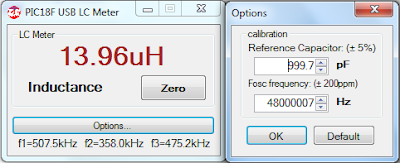 added "Calibration option" ( same PIC18F firmware )
# edit (08-14-11)
V1.2 -> updated host-side application,
-> should now work both on 32-bit OS and 64-bit OS hosts.

 |
 |
diagram using internal Analog Comparator and Timer Peripherals of PIC18:

schematic with actual values:

*simulation on Proteus 7 is NOT working (particularly the LC oscillator part and internal pull-up on RB0)
download link (HEX and PC app): PIC18F2550_USB-HID_LC-Meter.zip
elab.ph forum link: PIC18F2550 USB LC Meter
# edit (10-20-10)
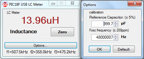
- reference capacitance range is 1.0nF +/- 5%
- Fosc (20MHz crystal with PLL) frequency range is 48MHz +/- 200ppm
# edit (08-14-11)
V1.2 -> updated host-side application,
-> should now work both on 32-bit OS and 64-bit OS hosts.
Thursday, September 23, 2010
Android Bluetooth Oscilloscope
*This application is tested only with Samsung Galaxy GT-i5700 Spica (rooted Android 2.1 OS, i570EXXJD1 Baseband version).
The transmitter circuit uses Microchip's dsPIC33FJ16GS504 for the analog-to-digital conversion of the input signals on two channels. The processed data on the dsPIC are then transmitted to the phone (for waveform display) via the LMX9838 bluetooth SPP module.
specs/ranges:
- time per division: {5us, 10us, 20us, 50us, 100us, 200us, 500us, 1ms, 2ms, 5ms, 10ms, 20ms, 50ms }
- volt per division: {10mV, 20mV, 50mV, 100mV, 200mV, 500mV, 1V, 2V, GND}
- analog input (depends on external pre-amplifier configuration): {-8V to +8V }
The source codes for the bluetooth communication is based on Bluetooth Chat example from http://developer.android.com. That example contains three java source files. And, I've completely copied the "DeviceListActivity.java", which is used for searching remote bluetooth devices. Then I've modified the "BluetoothChatService.java" to use only the RFCOMM Client functions, and used the well-known UUID "00001101-0000-1000-8000-00805F9B34FB" for the Bluetooth RFCOMM/SPP.
For the plotting of waveforms, I'm using SurfaceView object to draw on its canvas. This tutorial found on www.helloandroid.com helps me a lot for this task: "How to use canvas in your android".

The rest of the job mainly involves porting of my previous Python S60 script to JAVA language. It was too painful on my side, because I had to convert a single script file to multiple java + xml source files! Nonetheless, it was a good experience for me on learning the Android SDK (JAVA programming).
Project source codes for Android and dsPIC (with APK and HEX) :
AndroidBluetoothOscilloscope.zip
Electronicslab.ph forum link : Android Bluetooth Oscilloscope
Here are some interesting projects that are also based on the Bluetooth Chat example:
Bluetooth Controlled Model Car
SPRIME
Special thanks to:
Samdroid Forum for the customized/rooted firmwares for our Spica.
Tipidcp Spica users for sharing their tips and experiences with this android phone.
----------------------------------------------------------------------
#edit (10-15-2010)
Here's now my circuit. Nothing special on it, all are based on existing circuits.

*If you prefer to change the input range via the op-amp preamp, the computation is located on the "adc.xmcd" file.
*You can use other SPP bluetooth modules aside from LMX. (accdg to manufacturer, it's already obsolete)
----------------------------------------------------------------------
#edit (9-14-2011)
It's almost a year now, and yet some people are still interested in this project (considered to be obsolete). So I've decided to place the source repository also on Google Code site. You can either Browse or use git to have your own local copy:
git clone https://code.google.com/p/android-bluetooth-oscilloscope/
See also the Changes, if you want also to learn on how to modify the code. I've started the first 'commit' with a simple "hello world" from the SDK project template. And then changes were made until the desired final oscilloscope application is achieved.
Wednesday, July 7, 2010
ZiLOG Z8F64xx Timer Calculator
Sample code generator for ZiLOG's Z8F64xx Z8 Encore family of 8-bit Flash MCU's. Tested only with ZDSII v4.11 (C compiler-v3.60) on Z8F6423 running at 20MHz crystal. It's expected to work also with other parts, like Z8F6421 of e-Gizmo's IRC Slimboard. It generates sample codes of "timer interrupt" and "pulse width modulation(pwm)" for TIMER0, TIMER1, TIMER2, and TIMER3 peripherals. Please refer to the datasheet("part selection guide" table) of this family to see what timer peripherals are available on a particular part.
-----------------------------------------------------------------
-----------------------------------------------------------------
-----------------------------------------------------------------
note: I'm a newcomer to javascript. Please notify me of found "bugs" in these code makers.-----------------------------------------------------------------
Sunday, June 27, 2010
Bluetooth Controlled Mobot
Bluetooth Controlled Mobot using Z8F0823 and LMX9838.
 It's supposed to be my entry for a friendly competitions of "sumobots". But, I wasn't able to make it "autonomous" on time for the event. It only have four sensors on each corner to detect "black" lines, but no sensor for detecting an opponent. And so that I can still test the hardware, I just made it manually controllable by using my phone's bluetooth. The bluetooth module is the same circuit I used in my BT minibot . I also used the same python S60 script for my N6120c (Symbian phone) controller.


forum link: Filipino Version of Robot Wars


forum link: Filipino Version of Robot Wars
Tuesday, June 1, 2010
Mini-STM32 WAVE Audio Player
Mini-STM32 SD/MMC WAV (RIFF-WAVE-LPCM format) Audio Player with Spectrum Display
Simple SD Audio Player with an 8-pin IC by ChaN
DSP (FFT) libraries for Cortex M3 by Ivan Mellen
CooCox CoOS real-time multi-task OS
minimal hardware modification:
demo video:
Project files: Mini-STM32 WAVE Audio Player.rar
forum link: Mini-STM32 board

Simple SD Audio Player with an 8-pin IC by ChaN
DSP (FFT) libraries for Cortex M3 by Ivan Mellen
CooCox CoOS real-time multi-task OS
minimal hardware modification:
 |  |
demo video:
Project files: Mini-STM32 WAVE Audio Player.rar
forum link: Mini-STM32 board
Saturday, May 22, 2010
PIC18F SD WAV Audio Player
As inspired by Simple SD Audio Player by ChaN, this project uses Microchip's PIC18F2550 to read RIFF WAVE files, and display some file information on the N6610 LCD; And then it will play the audio itself through PIC's PWM with a simple RC filter on the output pin. The hardware actually comes from my previous project, and I just attached a ready-made audio amp (w/ speaker) for the demo.
Schematic:
Due to PIC's peripheral limitations, I only set the PWM frequency to 187.5kHz and not the 250kHz carrier frequency originally used by ChaN, because it's the maximum PWM frequency than can still get an 8-bit resolution of the duty cycles (=48MHz/256). It is also possible to use R-2R ladder in stead of (low-pass) filtering the PWM output since there still enough unused digital output pins for this approach.
On the software part, I wasn't able to make a good data buffering as good as what ChaN did. It's noticeable with WAVE files with higher bit-rates (=SampleRate*NumChannels*BitsPerSample). Nevertheless, it can still support up to 48kHz sampling rate, but with only Mono channel and 8-bits/sample resolution.
demo video:
Source code(PICC-18) with and without LCD: PIC18 SD WAV Audio Player
My on-going project: currently porting the code to STM32F103RB for additional features.
Some useful software (shareware) tools:
TextAloud - Text to Speech software
Switch Sound File Converter-multi format audio file converters
Schematic:

Due to PIC's peripheral limitations, I only set the PWM frequency to 187.5kHz and not the 250kHz carrier frequency originally used by ChaN, because it's the maximum PWM frequency than can still get an 8-bit resolution of the duty cycles (=48MHz/256). It is also possible to use R-2R ladder in stead of (low-pass) filtering the PWM output since there still enough unused digital output pins for this approach.
On the software part, I wasn't able to make a good data buffering as good as what ChaN did. It's noticeable with WAVE files with higher bit-rates (=SampleRate*NumChannels*BitsPerSample). Nevertheless, it can still support up to 48kHz sampling rate, but with only Mono channel and 8-bits/sample resolution.
demo video:
Source code(PICC-18) with and without LCD: PIC18 SD WAV Audio Player
My on-going project: currently porting the code to STM32F103RB for additional features.
Some useful software (shareware) tools:
TextAloud - Text to Speech software
Switch Sound File Converter-multi format audio file converters
Tuesday, May 11, 2010
PIC SD BMP Reader II
It is similar to my first PIC SD BMP Reader , and almost the same circuit except for the LCD. This time I now use a Nokia 6610 LCD. The LCD is capable of displaying 4096 colors, but for code simplicity I just operate it at 8-bit (256 colors) resolution.
Diagram:
This project is capable of reading bitmap file using common format (24-bit per pixel), with size (width and height) equal to or less than 132 pixels at both side.
demo video:
Source code + diagram: PIC18 SD BMP Reader 2.rar
similar project at Hack-a-day: How-to: Digital picture frame, 100% DIY
-it uses PIC24FJ64 in stead of pic18f2550
Diagram:

This project is capable of reading bitmap file using common format (24-bit per pixel), with size (width and height) equal to or less than 132 pixels at both side.
demo video:
Source code + diagram: PIC18 SD BMP Reader 2.rar
similar project at Hack-a-day: How-to: Digital picture frame, 100% DIY
-it uses PIC24FJ64 in stead of pic18f2550
Saturday, May 8, 2010
PIC18 SD BMP Reader
This project uses Microchip's PIC18F2550 and Nokia 3310 LCD to read and display images from BMP files on the SD/MMC cards. Although the display itself is monochrome, it still supports 24-bpp (bits per pixel), 8-bpp, 4-bpp, and 1-bpp (monochrome) Bitmap files (*.BMP) with size of 84x48 pixels. It uses the Petit FAT File System Module by ChaN.
Diagram and simulation:
Actual circuit:

Demo video:
forum link: Petit FAT File System (w/ Proteus ISIS simulation)
Source code(PICC18) + simulation(ISIS) + others: PIC18 SD BMP Reader.rar
references for BMP file format:
Wiki BMP file format
atlc.sourceforge bmp format
MSDN Types of Bitmaps
Diagram and simulation:

Actual circuit:
 |  |

Demo video:
forum link: Petit FAT File System (w/ Proteus ISIS simulation)
Source code(PICC18) + simulation(ISIS) + others: PIC18 SD BMP Reader.rar
references for BMP file format:
Wiki BMP file format
atlc.sourceforge bmp format
MSDN Types of Bitmaps
Saturday, April 24, 2010
Mini-STM32 Digital Picture Frame
The original source code for this project is copied from Martin Thomas' Simple STM32 Digital Picture Frame


Some of the minor modifications I made were:
demo video:
Modified Source Code (Keil RVMDK + uVision 4): Digital Picture Frame.rar
The application reads picture-files in standard Windows BMP-format from a SD-Card and shows them on a 2.8" color-LCD-module (320*240 px).The application also uses the FAT File System Module by Chan, on which M. Thomas ported to work on STM32 SPI interface. Additional information about this project can be found on the link above.


Some of the minor modifications I made were:
- I've modified the LCD driver so that it will work on my unit. My unit got the ILI9320 LCD controller.
- I didn't utilize the USART interface (but this can be easily enabled in the code). In stead of sending the "information" through this interface , some of them are being displayed on the LCD itself (e.g. bitmap filenames).
- I've enabled the two push-buttons on the board. The first one toggles between "Play" and "Pause"; and the other one is to "Restart" the "slide-show" from the beginning.
demo video:
Modified Source Code (Keil RVMDK + uVision 4): Digital Picture Frame.rar
Friday, April 16, 2010
FreeRTOS on Mini-STM32
FreeRTOS Demo on Mini-STM32 kit (STM32F103RBT6 with 2.8" TFT LCD).

My initial attempt of porting the FreeRTOS Demo was considerably a success. But later on, I found out that the version used of STM32 standard peripheral library was already obsolete. And so I didn't anymore continue with that. In stead, I opt to use the latest Firmware version which is v3.2.0 (Mar-2010), and combine it with the latest FreeRTOS source code - v6.0.4.
It wasn't easy for me to start the Keil uVision project from scratch (almost). On the brighter side, I already got familiarized with STM32 code libraries because of this activity. It's mostly trial-and-error approach. But luckily I stepped into this guide of porting the FreeRTOS source: Running FreeRTOS on the Keil MCBSTM32 Board with the RVMDK Evaluation Tools
Here's the result. After few seconds of displaying the "Powered by FreeRTOS" message, the demo will now display the status of all tasks. If there's no error occurred, it will show "PASS" and the 'jitter' in the processing of timer interrupt (timertest.c). For the USART test (comtest.c), there's a "loopback" test of transmitted and received characters. Simply short the pins 2 and 3 (RX and TX) of CON1 in the Mini-STM32 board. Otherwise, it will show "ERROR IN COM TEST" message.
Source Code (Keil RVMDK + uVision 4): FreeRTOS on MINI-STM32.rar

My initial attempt of porting the FreeRTOS Demo was considerably a success. But later on, I found out that the version used of STM32 standard peripheral library was already obsolete. And so I didn't anymore continue with that. In stead, I opt to use the latest Firmware version which is v3.2.0 (Mar-2010), and combine it with the latest FreeRTOS source code - v6.0.4.
It wasn't easy for me to start the Keil uVision project from scratch (almost). On the brighter side, I already got familiarized with STM32 code libraries because of this activity. It's mostly trial-and-error approach. But luckily I stepped into this guide of porting the FreeRTOS source: Running FreeRTOS on the Keil MCBSTM32 Board with the RVMDK Evaluation Tools
 |  |
Source Code (Keil RVMDK + uVision 4): FreeRTOS on MINI-STM32.rar
Friday, April 9, 2010
Mini-Term
I've recently bought a Mini-STM32 kit for the purpose of learning ARM-based MCUs. These development kits were from China and then locally distributed by DIY Hobbyist Corner at an affordable price.
After playing with the example codes, including the uCOS/uCGUI demo, I came up with this Mini UART (serial) Terminal application.

I just utilized the source/library for OS of the uCOS_DEMO since I still don't understand how it works. Luckily I got a copy of uCGUI manual and so I manage to make modifications on the existing sample GUIs (graphical user interface). And later, I'm also able to design my own GUIs.
The USART interface is not difficult to learn since it's almost similar to what other microcontrollers is using. Therefor, it's also easy "porting" the USART code (using standard C language) from my previous MCUs to this STM32 MCU.

The application uses the touch-screen capability of the kit for the keypad interface. However, because of the small LCD area, it's impractical to design the keypad as a full featured "qwerty" keyboard. What I did was just provide alternate characters for most of the existing keys.
"Caps" key pressed and USART baudrate chage:
"QWERTY" key toggled and MainForm minimized(showing desktop background):
Alternate keys/symbols and movable dialog:
It's also possible to use a "gender changer" (DB9 female to DB9 Male) on CON1 of the kit to make it resembles as a common PC serial port.
A problem may also raises because of the possibility that the touch-screen response will vary with different units. So, I added an optional "touch-screen calibrate" at start-up. This option can be found on "miniterm.h" header (the "calibration" code is also copied from one of the demo/example codes).
Source Code (using Keil RVMDK + uVision) download: mini-Term.rar
forum link: Mini STM32 with 2.8 LCD and touchscreen
After playing with the example codes, including the uCOS/uCGUI demo, I came up with this Mini UART (serial) Terminal application.

I just utilized the source/library for OS of the uCOS_DEMO since I still don't understand how it works. Luckily I got a copy of uCGUI manual and so I manage to make modifications on the existing sample GUIs (graphical user interface). And later, I'm also able to design my own GUIs.
The USART interface is not difficult to learn since it's almost similar to what other microcontrollers is using. Therefor, it's also easy "porting" the USART code (using standard C language) from my previous MCUs to this STM32 MCU.

The application uses the touch-screen capability of the kit for the keypad interface. However, because of the small LCD area, it's impractical to design the keypad as a full featured "qwerty" keyboard. What I did was just provide alternate characters for most of the existing keys.
"Caps" key pressed and USART baudrate chage:

"QWERTY" key toggled and MainForm minimized(showing desktop background):

Alternate keys/symbols and movable dialog:

It's also possible to use a "gender changer" (DB9 female to DB9 Male) on CON1 of the kit to make it resembles as a common PC serial port.

A problem may also raises because of the possibility that the touch-screen response will vary with different units. So, I added an optional "touch-screen calibrate" at start-up. This option can be found on "miniterm.h" header (the "calibration" code is also copied from one of the demo/example codes).
Source Code (using Keil RVMDK + uVision) download: mini-Term.rar
forum link: Mini STM32 with 2.8 LCD and touchscreen
Monday, February 22, 2010
MSI Wind 12 Internal HSDPA (3.5G) Modem Mod
Ever since Wind12 series was introduced in the market, I always see in most of the reviews for these products announcing that these units have SIM card slot found underneath the battery pack. Yes I'm also aware that the 3G modules are only optional, but when I checked my Wind U230 I noticed that the SIM slot actually has no SIM connector inside. Nevertheless, it is true that there's an extra PCIe-mini card slot (intended for 3G modem module) found beside the harddisk. This is a great candidate for circuit modding on which I've already made one. =)
I've dissected my Smart Bro (Huawei E1553) modem for the sake of this mod. Anyway, these USB dongles are relatively cheap nowadays. AFAIK, pcie-mini card-type modems cost 3-4 times more compared to usb-types. Before doing the actual mod, I was still not sure whether this will work on 3.3V supply instead of the common 5V of USB ports. Since I cannot find its electrical specs, I just test it on actual. And, fortunately, it works!

I'm using pins 36 and 38 of PCIE mini card connector for the USB functionality of this port. And for the USB supply, I tapped 3.3V and GND on capacitor C236.This 3.3V supply for the pcie-mini card is automatically turned off during system standby.
 There's also a disable pin function for the host to disable the pcie-mini card. It is W_DISABLE# on pin 20. It is held low during boot up of the unit. Also during boot-up, the BIOS will check if there's a load on the pcie-mini's 3V3 output. If it doesn't see any load on the 3V3 bus, the unit will cut-off the 3.3V supply all throughout. Therefor, pressing Fn+F10 keys combination without "load" on the 3V3 will not cause this pin to go to logic high. For now, I'm not utilizing this pin since my "enable circuit" is not yet working. The enable circuit is basically using a p-channel mosfet, which is the same with the bluetooth mod. However, the mosfet I currently have doesn't operate well with only -3.3V Vgs (i.e. doesn't turn on properly). BTW, the enable logic for this pin 20 is opposite of what the previous mod have. Meaning, low (0V) on pin 20 corresponds to "module disabled", and high (3.3V) is "enabled".
I was also got bothered of whether the internal antenna of the modem may not be able to get a good signal strength since Wind12 chassis has metal backbones and the plastic cover itself has conductive coatings. But, there was a U210-lite user who ask me to solder his usb hsdpa modem inside his unit. And I'm quite satisfied with the result even if we didn't wire and reposition the antenna of his modem.
I managed to get coaxial wires (hoping that these wires are similar to what WiFi adapters and actual 3G modems are using). Unfortunately, after finishing the mod and testing the modem, from the usual RSSI of -85dBm (before placing the modem inside the unit) it drops to -90dBm(sometimes -95dBm to -100dBm with SUN network) =( . I'm already anticipating this result. The important is that I can still surf the net (and other online stuffs) without the unexpected disconnection.
Actually, I'm not sure if the second one is really another antenna of this modem but assumed it is since it's not connected directly to GND. We even tested hsdpa modem without this and still works surprisingly.
I've placed the two antennas in between the touch pad and the right speaker, and put some spaced in between the two. I've also repositioned the modem in such a way that SIM card can easily be accessed by just removing the upgrade panel of this unit.
Finally, the complete internal hsdpa modem mod (somewhat "messy").

Fn+F10 combination is now working (the symbol appears on the bottom right of the screen). The LED indicator, which is shared with WiFi, turns yellow. It turns to blue for WiFi and light-blue when both are enabled. (note: my hsdpa modem is always enabled in my present mod)
----------------------
03/01/10 update:
Now I have the extra time to revisit this mod. It seems that it's better (in term of signal reception) for the second antenna(?) to be soldered directly to usb modem instead of using coax wire. Below is my latest adjustment. It looks "presentable" now compared to the previous circuit.
I also tried using different mosfet (IRLML5103 SOT23 package) for the enable/disable function. Although I can now toggle the whole circuit by Fn+F10 keys, it's not a full success yet since my U230 encounters frequent usb disconnection of this modem. I'm not sure of the exact reason of this problem, so I just put back the previous hardware (i.e. Vcc supply) configuration.
I've dissected my Smart Bro (Huawei E1553) modem for the sake of this mod. Anyway, these USB dongles are relatively cheap nowadays. AFAIK, pcie-mini card-type modems cost 3-4 times more compared to usb-types. Before doing the actual mod, I was still not sure whether this will work on 3.3V supply instead of the common 5V of USB ports. Since I cannot find its electrical specs, I just test it on actual. And, fortunately, it works!

I'm using pins 36 and 38 of PCIE mini card connector for the USB functionality of this port. And for the USB supply, I tapped 3.3V and GND on capacitor C236.This 3.3V supply for the pcie-mini card is automatically turned off during system standby.
 |  |
 There's also a disable pin function for the host to disable the pcie-mini card. It is W_DISABLE# on pin 20. It is held low during boot up of the unit. Also during boot-up, the BIOS will check if there's a load on the pcie-mini's 3V3 output. If it doesn't see any load on the 3V3 bus, the unit will cut-off the 3.3V supply all throughout. Therefor, pressing Fn+F10 keys combination without "load" on the 3V3 will not cause this pin to go to logic high. For now, I'm not utilizing this pin since my "enable circuit" is not yet working. The enable circuit is basically using a p-channel mosfet, which is the same with the bluetooth mod. However, the mosfet I currently have doesn't operate well with only -3.3V Vgs (i.e. doesn't turn on properly). BTW, the enable logic for this pin 20 is opposite of what the previous mod have. Meaning, low (0V) on pin 20 corresponds to "module disabled", and high (3.3V) is "enabled".
I was also got bothered of whether the internal antenna of the modem may not be able to get a good signal strength since Wind12 chassis has metal backbones and the plastic cover itself has conductive coatings. But, there was a U210-lite user who ask me to solder his usb hsdpa modem inside his unit. And I'm quite satisfied with the result even if we didn't wire and reposition the antenna of his modem.
I managed to get coaxial wires (hoping that these wires are similar to what WiFi adapters and actual 3G modems are using). Unfortunately, after finishing the mod and testing the modem, from the usual RSSI of -85dBm (before placing the modem inside the unit) it drops to -90dBm(sometimes -95dBm to -100dBm with SUN network) =( . I'm already anticipating this result. The important is that I can still surf the net (and other online stuffs) without the unexpected disconnection.
 |  |
 |  |
I've placed the two antennas in between the touch pad and the right speaker, and put some spaced in between the two. I've also repositioned the modem in such a way that SIM card can easily be accessed by just removing the upgrade panel of this unit.
 |  |
Finally, the complete internal hsdpa modem mod (somewhat "messy").

Fn+F10 combination is now working (the symbol appears on the bottom right of the screen). The LED indicator, which is shared with WiFi, turns yellow. It turns to blue for WiFi and light-blue when both are enabled. (note: my hsdpa modem is always enabled in my present mod)
 |  |
----------------------
03/01/10 update:
Now I have the extra time to revisit this mod. It seems that it's better (in term of signal reception) for the second antenna(?) to be soldered directly to usb modem instead of using coax wire. Below is my latest adjustment. It looks "presentable" now compared to the previous circuit.
 |  |
Subscribe to:
Posts (Atom)