*This application is tested only with Samsung Galaxy GT-i5700 Spica (rooted Android 2.1 OS, i570EXXJD1 Baseband version).
The transmitter circuit uses Microchip's dsPIC33FJ16GS504 for the analog-to-digital conversion of the input signals on two channels.
The processed data on the dsPIC are then transmitted to the phone (for waveform display) via the LMX9838 bluetooth SPP module.
specs/ranges:
time per division: {5us, 10us, 20us, 50us, 100us, 200us, 500us, 1ms, 2ms, 5ms, 10ms, 20ms, 50ms }
volt per division: {10mV, 20mV, 50mV, 100mV, 200mV, 500mV, 1V, 2V, GND}
analog input (depends on external pre-amplifier configuration): {-8V to +8V }
The source codes for the bluetooth communication is based on Bluetooth Chat example from http://developer.android.com.
That example contains three java source files. And, I've completely copied the "DeviceListActivity.java", which is used for searching remote bluetooth devices.
Then I've modified the "BluetoothChatService.java" to use only the RFCOMM Client functions,
and used the well-known UUID "00001101-0000-1000-8000-00805F9B34FB" for the Bluetooth RFCOMM/SPP.
For the plotting of waveforms, I'm using SurfaceView object to draw on its canvas.
This tutorial found on www.helloandroid.com helps me a lot for this task:
"How to use canvas in your android".
The rest of the job mainly involves porting of my previous Python S60 script to JAVA language.
It was too painful on my side, because I had to convert a single script file to multiple java + xml source files!
Nonetheless, it was a good experience for me on learning the Android SDK (JAVA programming).
Special thanks to: Samdroid Forum for the customized/rooted firmwares for our Spica. Tipidcp Spica users for sharing their tips and experiences with this android phone.
---------------------------------------------------------------------- #edit (10-15-2010)
Here's now my circuit. Nothing special on it, all are based on existing circuits.
*The dsPIC I have used is most probably NOT the best choice for this project because of the many left unused peripherals (extra pins). But, this is the only part readily available in my bin and it has the fastest ADC (2 x 2MSps) among the chips I have. *If you prefer to change the input range via the op-amp preamp, the computation is located on the "adc.xmcd" file. *You can use other SPP bluetooth modules aside from LMX. (accdg to manufacturer, it's already obsolete)
It's almost a year now, and yet some people are still interested in this project (considered to be obsolete). So I've decided to place the source repository also onGoogle Codesite. You can eitherBrowse or use git to have your own local copy:
See also theChanges, if you want also to learn on how to modify the code. I've started the first 'commit' with a simple "hello world" from the SDK project template. And then changes were made until the desired final oscilloscope application is achieved.
Sample code generator for ZiLOG's Z8F64xx Z8 Encore family of 8-bit Flash MCU's.
Tested only with ZDSII v4.11 (C compiler-v3.60) on Z8F6423 running at 20MHz crystal.
It's expected to work also with other parts, like Z8F6421 of e-Gizmo's IRC Slimboard.
It generates sample codes of "timer interrupt" and "pulse width modulation(pwm)"
for TIMER0, TIMER1, TIMER2, and TIMER3 peripherals.
Please refer to the datasheet("part selection guide" table) of this family
to see what timer peripherals are available on a particular part.
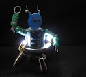
Bluetooth Controlled Mobot using Z8F0823 and LMX9838.
It's supposed to be my entry for a friendly competitions of "sumobots". But, I wasn't able to make it "autonomous" on time for the event. It only have four sensors on each corner to detect "black" lines, but no sensor for detecting an opponent. And so that I can still test the hardware, I just made it manually controllable by using my phone's bluetooth. The bluetooth module is the same circuit I used in my BT minibot . I also used the same python S60 script for my N6120c (Symbian phone) controller.
As inspired by Simple SD Audio Player by ChaN, this project uses Microchip's PIC18F2550 to read RIFF WAVE files, and display some file information on the N6610 LCD; And then it will play the audio itself through PIC's PWM with a simple RC filter on the output pin. The hardware actually comes from my previous project, and I just attached a ready-made audio amp (w/ speaker) for the demo. Schematic: Due to PIC's peripheral limitations, I only set the PWM frequency to 187.5kHz and not the 250kHz carrier frequency originally used by ChaN, because it's the maximum PWM frequency than can still get an 8-bit resolution of the duty cycles (=48MHz/256). It is also possible to use R-2R ladder in stead of (low-pass) filtering the PWM output since there still enough unused digital output pins for this approach. On the software part, I wasn't able to make a good data buffering as good as what ChaN did. It's noticeable with WAVE files with higher bit-rates (=SampleRate*NumChannels*BitsPerSample). Nevertheless, it can still support up to 48kHz sampling rate, but with only Mono channel and 8-bits/sample resolution.
It is similar to my first PIC SD BMP Reader , and almost the same circuit except for the LCD. This time I now use a Nokia 6610 LCD. The LCD is capable of displaying 4096 colors, but for code simplicity I just operate it at 8-bit (256 colors) resolution.
Diagram: This project is capable of reading bitmap file using common format (24-bit per pixel), with size (width and height) equal to or less than 132 pixels at both side.