

 |
 |
diagram using internal Analog Comparator and Timer Peripherals of PIC18:

schematic with actual values:

*simulation on Proteus 7 is NOT working (particularly the LC oscillator part and internal pull-up on RB0)
download link (HEX and PC app): PIC18F2550_USB-HID_LC-Meter.zip
elab.ph forum link: PIC18F2550 USB LC Meter
# edit (10-20-10)
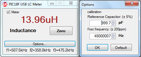
- reference capacitance range is 1.0nF +/- 5%
- Fosc (20MHz crystal with PLL) frequency range is 48MHz +/- 200ppm
# edit (08-14-11)
V1.2 -> updated host-side application,
-> should now work both on 32-bit OS and 64-bit OS hosts.


hi, Great concept
ReplyDeletesimply use the PC to read out instead of another LCD display.
however, don't you feel such an instrument can better be standalone, Mr YUS !
now I am trying to make a smaller version of Phil Rice design to be housed in DT38 model DMM cabinet. To make it possible , i have resorted to 8*2 display.
All the best and hope to see many more projects from constantun
regards
sarma
Very nice post, impressive. its quite different from other posts.
Deletedosing metering pump manufacturer in india
hi sarma,
ReplyDeleteIt's nice to hear from you again.
I agree with you, portable/standalone version is still the best option.
My main purpose for this project is to study also the "usb interfacing" with pic18.
Hope you'll finish your own version soon.
It will be better if you use smaller (lower-power) LCD.
best regards,
julius
It is a very useful article.
Deletemetering pump manufacturer in india
When loading HEX programmer you see this message.
ReplyDeleteError in HEX file-Fuse Line:397
:0100000024DB
YOU CAN HELP
Thanks
I like your post. This post really awesome and very helpful to me.
Deletedosing pump manufacturer in india | metering pump manufacturer in india | chemical dosing system | water treatment equipments | chemical dosing system | electromagnetic & motorised dosing pumps
YUS, I totally agree with you.
ReplyDeleteIf we get a glass display with the type of legend we need to display suffixes to the measured values, it is the best. In that direction, i sincerely feel that your earlier design with mobile phone TFT display is compact and superior.
I have practically settled for Phil Rice design but with L&C selection using a relay. There are no hanging wires from main board to mechanical switch and back.It is working very fine with 16*1 display. BTW, what new projects did you take up?
regards
sarma
It's been good to see your blog when I always look for such type of blogs.
Deletedosing pump manufacturer in india | water treatment equipments | chemical dosing system
Hi.
ReplyDeletewhat is maximum inductance/capacitance measured by USB LC meter?
regards
Dali
Thank you so much for your post.
Deletewater treatment equipments | chemical dosing system | dosing metering pump manufacturer in india | metering pump manufacturer in india | chemical dosing system
Hello,
ReplyDeleteIs it possible to get a copy of the source codes for PIC and host (C#)?
I would like to add a LCD to this great project. ebpalomino@hotmail.com.
A huge thanks to you. Keep sharing and updating more with us.
Deletemetering pump manufacturer in india | chemical dosing system | dosing pump manufacturer in india
hi ebpalomino,
ReplyDeletethe firmware code for the PIC18 and the C# code for the host are based only on the "USB Device - HID - Custom Demos" of Microchip's Application Libraries. I just made some modifications. So, it's better to start from the original code of microchip.
rgds,
julius
I am expecting such types of more post.
Deletedosing pump manufacturer in india | metering pump manufacturer in india | chemical dosing system | water treatment equipments | chemical dosing system | electromagnetic & motorised dosing pumps
hi,
ReplyDeleteit's the what i was looking for,most PIC based LC meters has LCD,can you plz give me the hex for 18F4550?because my development board got that
Could you post the configeration bits for the 18f2550 as i get error in pickit 2 saying that it cannot find config bits in hex file
ReplyDeleteIf i burn the hex with default config bits the the usb is not working at all
mine does also not work and I dont know why. I have looked data and clock lines with osciloscope and there are some data send but no response from program.
Deletehello
ReplyDeleteWhere possible i buy this meter
PIC18F USB LC Meter
good jop
Hello,
ReplyDeleteI need vb source code for this project..
please give
thanks in advance!
Best Regards
Hasnain
Hi,
ReplyDeleteI too need the config bits for the PK2 :D
i tried to guess those,is this correct,
http://img407.imageshack.us/img407/770/82523799.jpg
Hi,
ReplyDeleteI've built this successfully using config words i guessed in a previous comment,
I wrote a blog post too about this wonderful design.Thank you YUS :D
http://lab.buddika.info/2012/03/homemade-usb-lc-meter.html
Hello
ReplyDeleteCan you send me the source code of the
pic microcontroller?
I would like to modify it because I need
some device what is indicate on output line
when the inductance is over than presetted
values.
Thax
mail:tpucz@juropnet.hu
would it be possible to get the full hex with config bits included, as i have built board and having problems setting bits shown in picture..
ReplyDeletethis would be very much appreciated
Paul
their is no polarity detail of C2 capacitors
ReplyDeleteso i need use 20Mhz or 48hmz oscilator?
ReplyDeleteDo you know the name of that oscillator? I cant understand how it works...
ReplyDelete@Paul He won't give the source and I can't d/l from 4shared, so I think of
ReplyDelete1) Get known with USB interfacing to pic 18F2550
2) Get to know how it works & make my own program.
Once you have own source code, it becomes possible to improve the hardware also.
For Angello:
ReplyDeletehttp://www.qrz.lt/ly2bok/Konstrukcijos/USB%20LC%20meter/USB%20LC%20matuolklis.htm
Hello Friend,
ReplyDeleteCan you please send me source file if it is in C? I shall be thankful to you.
I am unable to download from 4shared due to having non paid account.
IFFI
iffi_pakistan@hotmail.com
Can i have the source code of the pc application?
ReplyDeleteI have built the circuit.it is working except it has a accuracy problem.I can make it more accurate if i got the mathematical conversion happening in the application.Or any link related would be helpful.The link about f1,f2,f3 is not working.Fixing the link also would do..
USB DEVICE not detected ! i made the circuit, installed the hex file into the 18f2550 via pickit2 and inserted it into ckt ! when i connected it via usb port ! its unable to install its drivers nor the program is detecting it ?? :(
ReplyDeleteI read your project's description
ReplyDeleteand i intend to build a similar project adding a resistance meter for my end of year project. i wish to have the C code to work on it.
thanks
hi Yus,
ReplyDeleteI'd like to adapt this circuit to operate with a lcd display for that, you could provide the code * .c?
thanks
Thanks for circuit and code.
ReplyDeleteHello.
ReplyDeleteIm gonna build this project of yours and I was wondering what kind of capacitors are C2 and C3? are they regular or tantalium cos in some other LC meter with 16F628A theese two are tantalium.
Hello.
ReplyDeleteI have build this LC meter but when I program the pic using easypic6 and put it on to my pcb and plug it into pc it doesn work like it doesnt wanna connect with the program. Drivers are installed automatic. The strange thing is that Microchip Custom USB Device driver doesnt wanna work.Code 10
is this hex file fuesed with bootloader or I have to load bootloader myself?
ReplyDelete